Structural Design · FEA · Modal Analysis
Individual Undergraduate Thesis
Steel Gate Structural Design & Dynamic Analysis
Structural Design · Finite Element Analysis · Modal Analysis
Structural design and numerical analysis of a 2.0 m × 2.0 m flat steel gate, combining engineering calculations, finite element modelling, stress and deformation analysis, and modal analysis.
Year
2024
Type
Individual Undergraduate Thesis
University
Hohai University
Tools
CAD · ANSYS APDL
My Role
Structural Design · Engineering Calculations · Finite Element Analysis
01 / Overview
Completed as an individual undergraduate thesis at Hohai University in June 2024, the project developed and checked a 2.0 m × 2.0 m sliding flat steel gate. The study combines code-based engineering calculations with an ANSYS APDL model to examine load transfer, structural response and dynamic characteristics.
02 / Design Requirements
The documented design basis uses a 2.0 m × 2.0 m gate opening, a 6 m design water depth, a 2.2 m water-stop height and sliding supports. Q235B steel is specified for the principal structural members, with material allowables and stiffness checks taken from the cited hydraulic steel-gate design standards.
03 / Structural Configuration
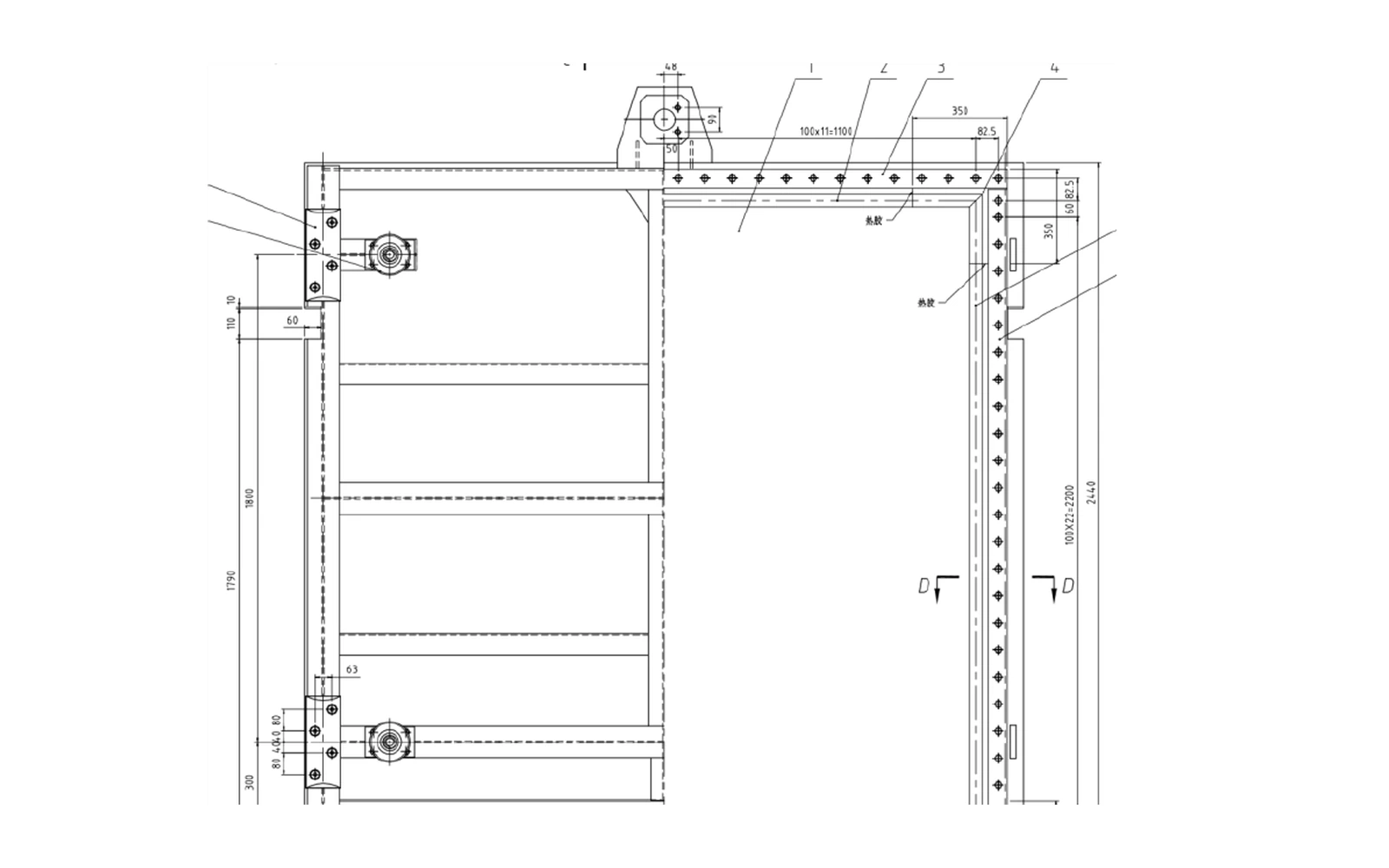
The selected arrangement places the skin plate on the upstream face and supports it with horizontal primary and secondary beams, vertical members, side beams and roller assemblies. The configuration drawing defines the panel, load-carrying beam system, support geometry and interfaces needed for lifting and guided travel.
04 / Engineering Calculations
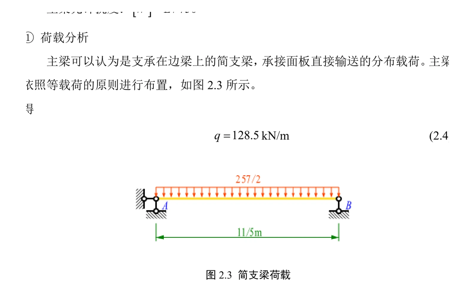
Hydrostatic pressure was converted into member loads before sizing the plate and supporting beams. The thesis checks plate thickness, primary and secondary beams, side beams, rollers and guide-track components through bending, shear, combined-stress and deflection calculations; the selected panel thickness is 12 mm.
05 / Finite Element Model
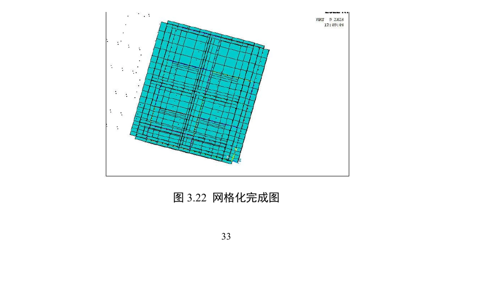
A three-dimensional ANSYS APDL model idealizes the plate with shell elements and the supporting members with beam elements. Material properties, keypoints, lines and areas were defined before meshing, applying hydrostatic pressure and gravity, and constraining the modeled support locations.
06 / Stress and Deformation Analysis
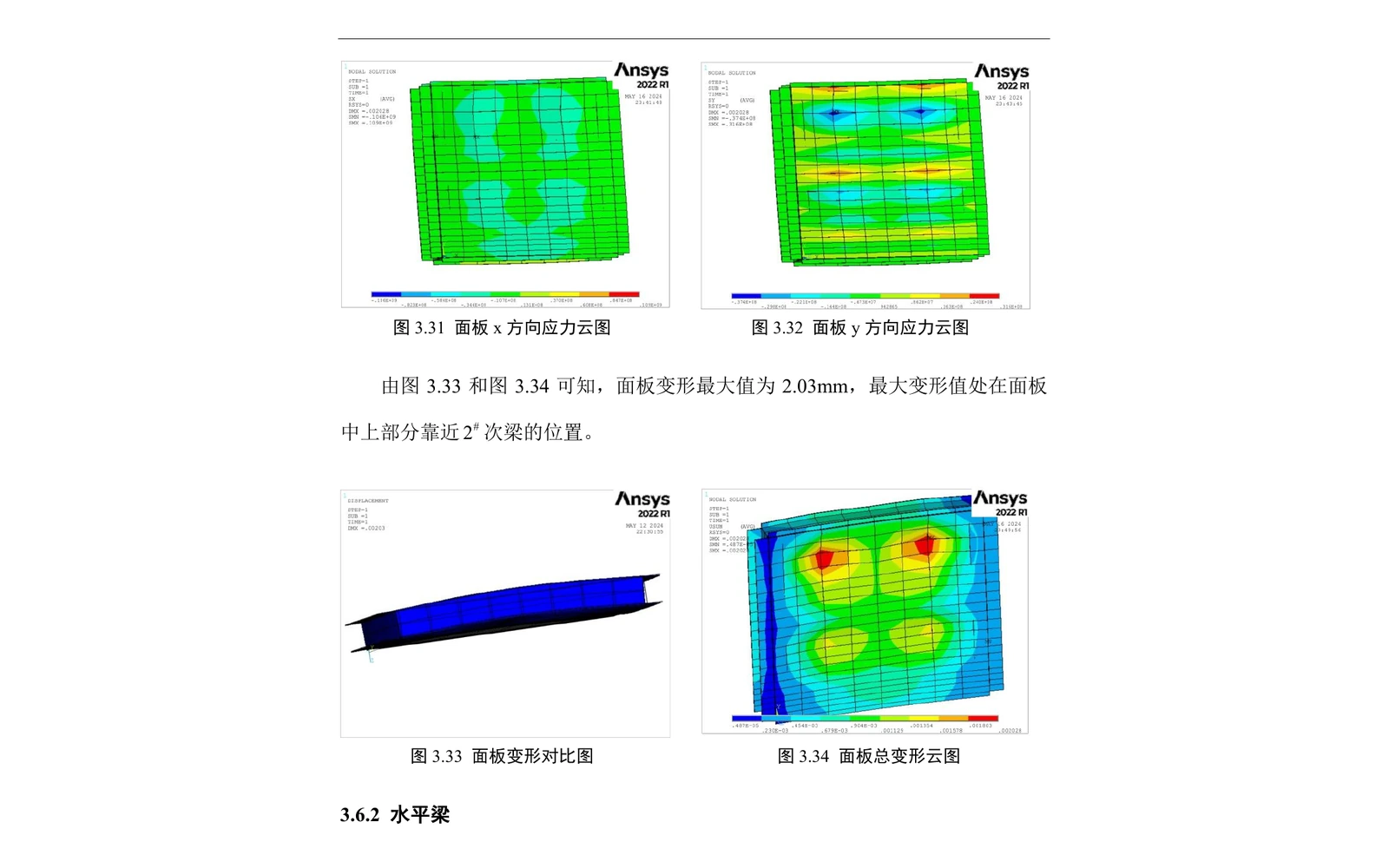
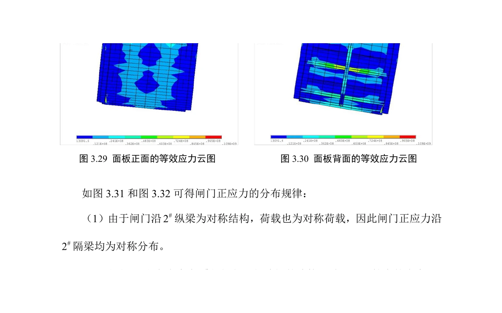
The numerical results report a maximum gate-panel equivalent stress of 113 MPa, below the 205 MPa allowable used in the thesis, and a maximum panel deformation of 2.03 mm near the central region between vertical beams. Beam-level stress and displacement results were also reviewed against the corresponding allowable values.
07 / Modal Analysis
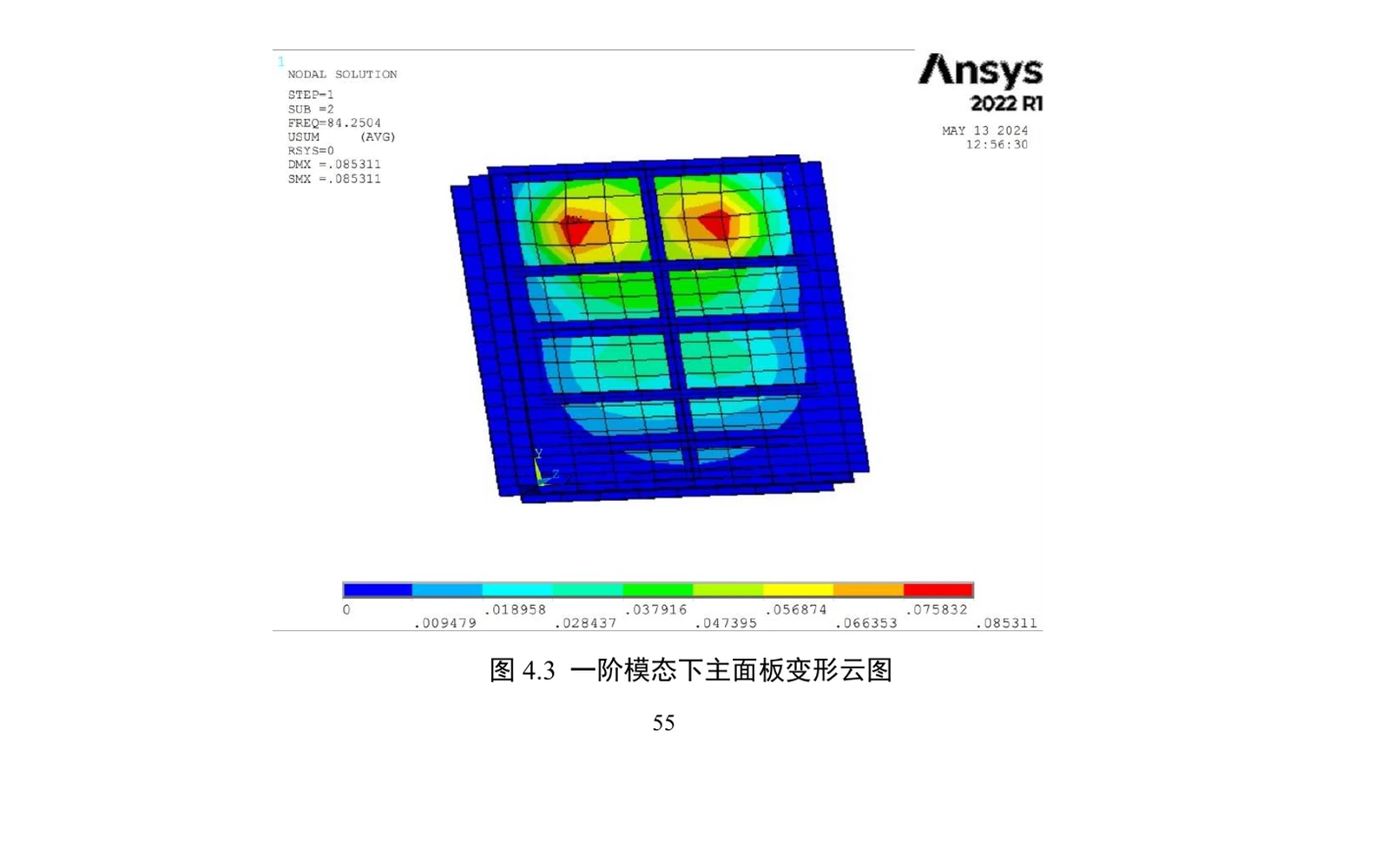
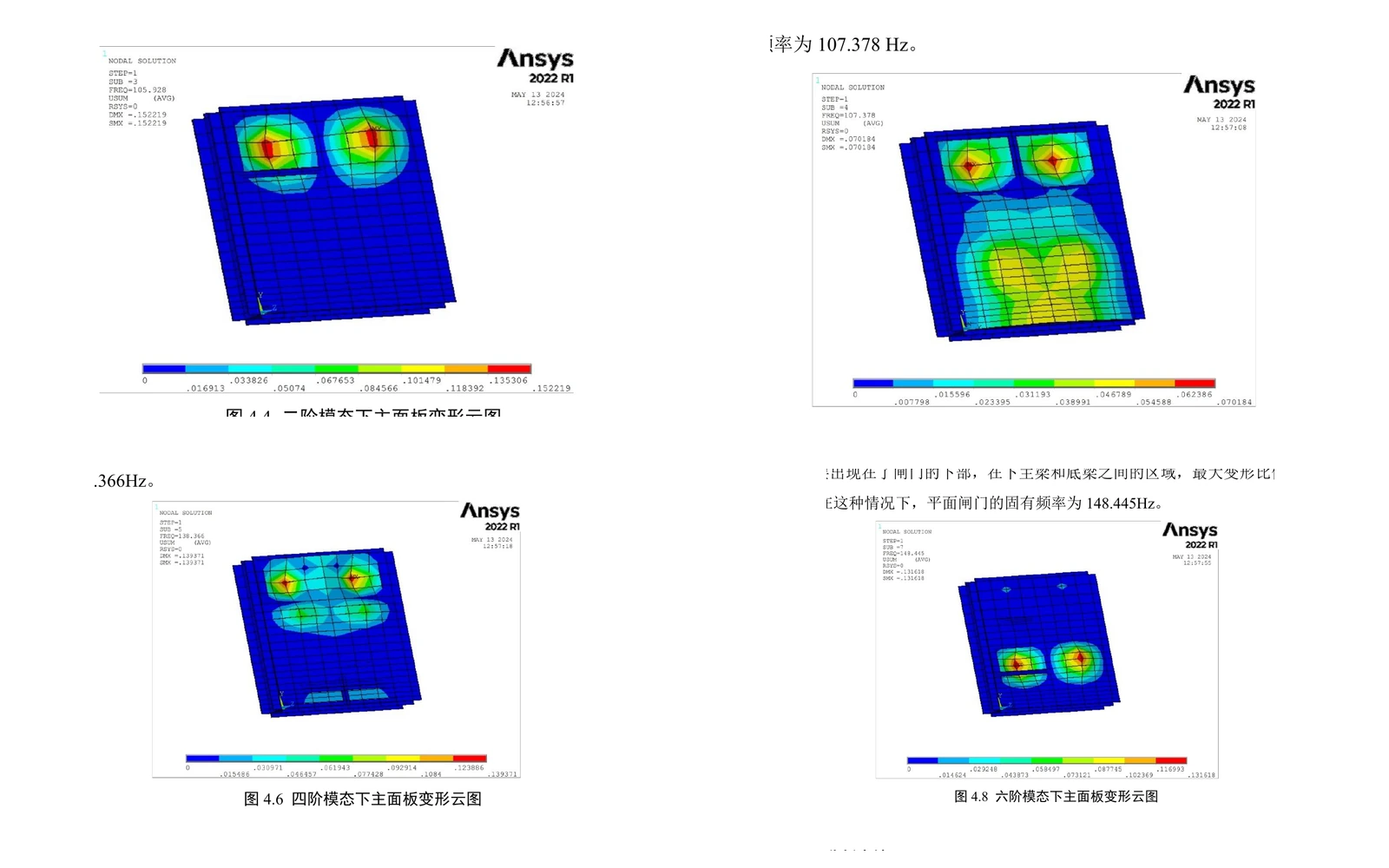
The first six documented natural frequencies are 84.2504, 105.928, 107.378, 138.366, 138.845 and 148.445 Hz. The plotted mode shapes show how deformation moves between the upper beam-panel regions and other areas of the gate as the mode order increases.
08 / Results and Engineering Interpretation
The analytical sizing and APDL results provide a consistent engineering check of the selected arrangement: the reported stresses remain below the thesis allowables and the deformation pattern identifies the more flexible panel and beam regions. The evidence presented here is analytical and numerical; no physical validation is claimed.
- 012.0 m × 2.0 m sliding flat gate
- 0212 mm selected skin-plate thickness
- 03113 MPa reported maximum panel equivalent stress
- 042.03 mm reported maximum panel deformation
09 / Key Learnings
The thesis reinforced the connection between classical structural calculations and finite element interpretation. It also showed how element idealization, boundary conditions, load application and mode-shape reading influence whether a numerical model supports a credible engineering decision.
Next Project · 04